DMX-Controlled RGB Spots
— dj, dmx, electro, electronics, laser, led, lighting, party, rgb, spots — 3 min read
I've been working — on and off for about a year and a half — on a project of developing some DMX-controlled RGB spots.
If you're not familiar with it, DMX (aka DMX512-A) is a standard that defines how a controller can talk to some devices, for show control. The standard defines the physical (connector, cable), electrical (based on RS-485) and logical (protocol, timings) layers, and is fairly straightforward. The connection (except for the mostly-unused RDM extension), is unidirectional, and runs over 5-pin XLR cables (this was chosen by the standards committee to reduce the chances of equipment damage in typical setups, where 3-pin XLR connectors are used for audio, even though only 3 of the 5 pins are really used).
The goal of the project was to design, assemble and test a system that controls 16 full-RGB (red/green/blue) high-power LED spots. Some friends were throwing a big party for Halloween at their house a couple of weeks back, and I was DJing for the entire evening, so I figured it would be a good time to test my system! I borrowed a friend's ENTTEC Open DMX box (USB to DMX converter), and setup Freestyler DMX on my laptop, and programmed a few patterns in there, so I could control everything throughout the evening while I was DJing and taking requests…
After finishing to set everything up over there, I recorded a video of some of my first tests. You can see the result in the video below; the 16 spots are fixed to the ceiling (8 on each side of the room), and provide all the light, except for the laser, which is a cheap laser I bought a while back to test DMX control.
(note that I have replaced the audio with a synchronized version of the track that was playing, since the 5DmkII's microphone didn't sound very good with over 1000W of sound…!)
The party was quite a success, from the comments I have received, so I can't complain 🙂
The system itself is fairly simple, but the power resides in the fact that there is a single “brain” that controls all 16 spots, so it is much easier to have synchronized effects this way. The system consumes around 100W of power when full on (all 16 spots white).
This is the “brain” (the control board):
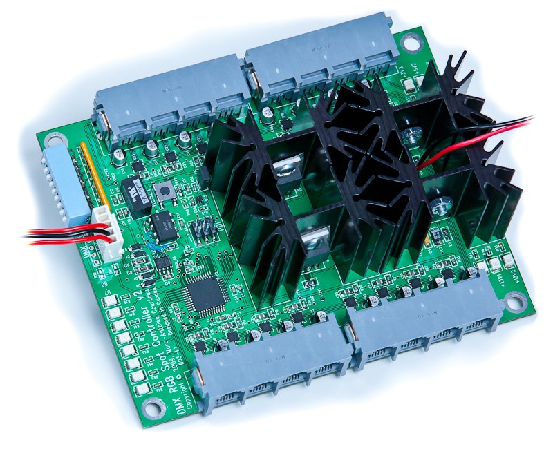
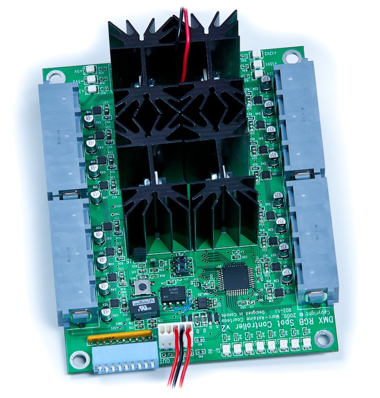
Not shown above is the 15V/10A power supply, and the XLR connector. Yes, the heat sinks are huge; that will teach me to use linear voltage regulators instead of switching regulators!
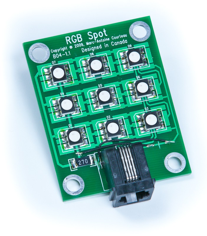
Then, the 16 spots are connected with telephone wires (cheap, and can withstand the current) to the sides of the board (as you can see above). This is what each spot looks like:
Now obviously, there is some wire-wrap on both boards. Nothing can be perfect the first time around 🙂 Hopefully, there won't be any wire-wrapping if I do an other revision (with more features, such as USB and/or Ethernet, and maybe more than 16 spots; the linear voltage regulators would also be replaced with switching regulators in an other revision).
Thanks for reading, and let me know what you think in the comments below!